PPG Heart Rate Sensor Explained: Optical Modules, Multi-LED Design, and Motion Compensation
How PPG heart rate sensors work inside wearables. Learn about multi-LED arrays, ambient light rejection, accelerometer fusion, and sensor module design.
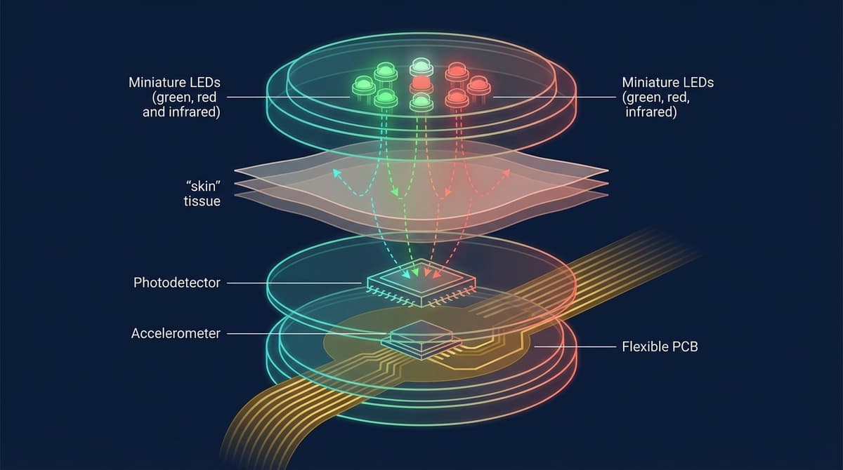
A PPG heart rate sensor is an optical module that combines LEDs, photodetectors, and signal processing electronics to measure pulse rate from the skin surface. Modern wearable heart rate sensors use multi-LED arrays with 2-8 LEDs at different wavelengths, paired with one or more photodetectors and an inertial measurement unit (IMU) for motion compensation. The entire module, including analog-to-digital conversion and ambient light cancellation, fits into a package smaller than a fingernail. This article explains what is inside these sensors, how they achieve clinical-grade accuracy, and what distinguishes one sensor module from another.
Anatomy of a PPG Heart Rate Sensor Module
A complete PPG heart rate sensor consists of several tightly integrated subsystems. Understanding each component explains why some devices perform better than others and why sensor design involves more engineering tradeoffs than most people realize.
LED Array
The LED array is the light source. It illuminates the tissue beneath the sensor, and the characteristics of the LEDs directly determine what the sensor can measure.
Number of LEDs: Consumer heart rate sensors range from 2 LEDs (budget fitness bands) to 8 or more (Apple Watch Ultra, Samsung Galaxy Watch). More LEDs provide better skin coverage. On a wrist, the position of capillary beds varies between people. An LED that sits directly over a good vascular bed for one person may miss it entirely on another wrist. By spreading multiple LEDs across the sensor face, the chances of at least some LEDs hitting productive tissue increase.
Wavelength selection: Green LEDs (520-570 nm) are the workhorse for heart rate. They produce the strongest pulsatile signal at typical wrist depths. Red (660 nm) and infrared (940 nm) LEDs are added for SpO2 measurement and for improved performance across skin tones. Some sensors include yellow or orange LEDs (590-610 nm) as additional data channels for multi-wavelength signal processing.
LED placement geometry: The spatial arrangement of LEDs relative to photodetectors matters. The optimal LED-to-detector spacing depends on the target tissue depth. For superficial capillaries (green light), 2-4 mm spacing works well. For deeper penetration (IR), wider spacing of 4-8 mm can capture signals from larger vessels. Some sensor designs use concentric rings of LEDs at different distances from a central photodetector.
For more on wavelength choices and their implications, see our PPG LED wavelength selection guide.
Photodetector
The photodetector converts optical signals into electrical current. Most PPG modules use silicon photodiodes with broadband sensitivity covering 400-1100 nm, matching the LED wavelengths in use.
Photodiode area affects sensitivity and noise. Larger photodiodes collect more light but also collect more ambient light. The optimal size balances signal collection against noise floor. Typical photodiode areas in wearable PPG modules range from 1 mm² to 5 mm².
Multiple photodetectors appear in higher-end sensors. Some designs use 2-4 photodetectors at different positions to provide spatial diversity. This allows the signal processing algorithm to select the detector with the best signal quality or combine multiple detector outputs for improved SNR. The Maxim MAX86916, for example, supports multiple photodiode inputs for this purpose.
Spectral filtering on the photodetector rejects light outside the wavelengths of interest. An optical bandpass filter in front of the photodiode reduces ambient light contamination while passing LED light. This is particularly important for outdoor use where broadband sunlight can saturate the detector.
Analog Front End (AFE)
The AFE is the electronic brain of the sensor module. It controls LED timing, amplifies the photodetector signal, converts it to digital, and performs initial signal conditioning.
LED driver: Controls when each LED turns on and off and at what current. In a multi-LED sensor, LEDs are time-multiplexed, meaning they fire one at a time in rapid sequence. A typical timing pattern might be: Green 1 ON for 50 microseconds, Green 1 OFF, Green 2 ON for 50 microseconds, Green 2 OFF, Red ON, Red OFF, IR ON, IR OFF, Ambient sample (all LEDs off). This cycle repeats at the sampling rate (e.g., 100 Hz = every 10 ms).
Transimpedance amplifier (TIA): Converts the photodiode's tiny current (nanoamps to microamps) into a measurable voltage. The TIA gain is programmable to match different LED powers and tissue optical properties.
Analog-to-digital converter (ADC): Digitizes the amplified signal. Resolution matters. A 16-bit ADC can resolve 65,536 levels. A 22-bit ADC provides over 4 million levels. Higher resolution lets the system capture the small AC pulsatile component (often <1% of the total signal) without quantization noise swamping the cardiac signal. Modern PPG AFEs use 18-22 bit ADCs.
Ambient light cancellation (ALC): During the LED-off phase of each time-multiplexed cycle, the AFE samples the ambient light contribution. This ambient sample is subtracted from the subsequent LED-on sample, removing the effect of sunlight, room lighting, and other environmental light sources. ALC is performed in the analog domain (before digitization) on most modern AFEs, which preserves ADC dynamic range for the actual PPG signal.
Ambient light interference is one of the most underappreciated challenges in wearable PPG design. Sunlight at the skin surface can deliver optical power orders of magnitude larger than the LED signal. Without effective ambient light rejection, the photodetector saturates and the PPG signal is lost.
Multiple mechanisms work together to fight ambient light:
Optical barriers. The sensor housing typically includes a raised ring or gasket around the LEDs and photodetector. This physical barrier prevents ambient light from reaching the detector through a direct path. Only light that has traveled through tissue (and back) reaches the detector.
Time-domain sampling. As described above, the AFE subtracts ambient-only samples from LED-on samples. This removes slowly varying ambient components.
Optical filters. Narrowband optical filters on the photodetector pass only wavelengths near the LED emission while rejecting broadband sunlight. A green-pass filter, for example, transmits 520-570 nm while blocking UV, blue, yellow, red, and IR.
Oversampling and averaging. By taking multiple LED-on/LED-off sample pairs per output sample and averaging, random noise from ambient light fluctuations is reduced. This is equivalent to increasing the effective ADC resolution.
For a full treatment of ambient light challenges and solutions, see our PPG ambient light interference guide.
Motion Compensation: The Accelerometer Fusion Pipeline
Motion artifacts are the dominant error source in wearable PPG heart rate measurement. The solution that has become standard across the industry is sensor fusion: combining PPG data with data from an inertial measurement unit (IMU, typically a 3-axis accelerometer and sometimes a 3-axis gyroscope).
Why Accelerometer Data Helps
When the sensor moves relative to the skin, the optical path changes. Blood is redistributed by mechanical force, air gaps form between the sensor and skin, and the tissue compression pattern shifts. All of these create large disturbances in the PPG signal.
The accelerometer measures the same motion that creates these artifacts. If the motion is known, its effect on the PPG signal can be estimated and subtracted.
The Fusion Pipeline
A typical accelerometer fusion pipeline for heart rate extraction works as follows:
1. Synchronization. PPG and accelerometer data are sampled at the same rate (or resampled to match) with aligned timestamps. Most integrated sensor modules handle this synchronization in hardware.
2. Frequency analysis. Both PPG and accelerometer signals are transformed to the frequency domain using overlapping windowed FFTs (e.g., 8-second windows with 2-second overlap).
3. Motion frequency identification. Dominant peaks in the accelerometer spectrum correspond to motion frequencies. Walking at 2 steps/second produces a fundamental at 2 Hz with harmonics at 4 Hz, 6 Hz, etc.
4. Spectral peak selection. In the PPG spectrum, peaks that coincide with accelerometer peaks are flagged as motion artifacts. The remaining peaks are candidates for the true heart rate frequency.
5. Tracking. A Kalman filter or similar tracker maintains an estimate of heart rate over time, using physiological constraints (heart rate cannot jump by more than ~20 BPM per second) to resolve ambiguous cases where motion and cardiac frequencies overlap.
6. Output. The tracked heart rate estimate is converted to BPM and reported, with a confidence metric based on signal quality assessment.
The TROIKA and JOSS Algorithms
Two published algorithms illustrate modern PPG motion compensation.
TROIKA (Tracking Recovery of Heart Rate from Wrist-Type PPG Signals during Intensive Physical Exercise) by Zhang et al. (2015) uses Singular Spectrum Analysis (SSA) for spectral decomposition combined with spectral peak tracking. It was one of the first algorithms to demonstrate accurate heart rate from wrist PPG during running. The original paper was published in IEEE Transactions on Biomedical Engineering.
JOSS (Joint Sparse Signal Recovery) treats PPG heart rate estimation as a sparse signal recovery problem. It uses compressed sensing to find the heart rate frequency in a joint PPG-accelerometer signal model.
Both algorithms and their successors demonstrate that aggressive motion compensation can reduce heart rate error during running by 50-70% compared to naive spectral estimation.
Sensor Module Comparison
The following table compares key characteristics of popular PPG sensor modules used in wearable heart rate products.
| Feature | Maxim MAX86150 | TI AFE4404 | ams AS7050 | ADI ADPD4101 |
|---|---|---|---|---|
| LEDs Supported | 3 (internal) | 3 (external) | 3 (external) | Up to 8 (external) |
| Photodiodes | 1 (internal) | 2 (external) | Up to 8 | Up to 8 |
| ADC Resolution | 19-bit | 22-bit | 20-bit | 16-bit |
| Sampling Rate | Up to 3200 Hz | Up to 500 Hz | Up to 500 Hz | Up to 4000 Hz |
| ECG Capability | Yes (1-lead) | No | No | No |
| Ambient Light Cancel | Yes | Yes | Yes | Yes |
| Package Size | 3.3 x 3.3 mm | 3.5 x 3.5 mm | 3.2 x 5.0 mm | 3.5 x 5.0 mm |
| Power (typical) | 0.5-1.5 mW | 0.3-1.0 mW | 0.5-2.0 mW | 0.3-1.5 mW |
| Key Differentiator | Integrated PPG+ECG | Low power, flexible | Multi-channel optical | High channel count |
For an in-depth look at sensor design tradeoffs for engineers, see our PPG sensor design guide.
Optical Design Considerations
Window Material
The optical window between the sensor and the skin affects performance. Most smartwatches use sapphire or hardened glass windows. The window material must transmit light at the LED wavelengths with minimal loss and withstand daily wear.
Anti-reflective coatings on the window surfaces reduce Fresnel reflection losses. Without coating, each glass-air interface reflects about 4% of the light. Two surfaces (entering and exiting the window) lose about 8% total. AR coating can reduce this to below 1%.
Cross-Talk Prevention
In a multi-LED multi-detector sensor, optical cross-talk occurs when light from one LED directly reaches the detector without passing through tissue. This creates a large, non-physiological signal that reduces dynamic range and can mask the cardiac component.
Cross-talk is prevented through:
- Physical barriers (light guides, opaque walls) between LED and detector cavities
- Time-division multiplexing so only one LED fires at a time
- Electronic subtraction of measured cross-talk during calibration
Skin Contact Interface
The interface between the sensor window and the skin surface determines optical coupling quality. Air gaps scatter light and reduce the signal reaching the detector. Many sensors use a slightly convex window that presses gently into the skin, displacing air and ensuring direct optical contact.
Some designs add a thin elastomer gasket around the optical window that compresses against the skin, creating a light seal that blocks ambient light entry from the sides while maintaining comfortable pressure.
Power Consumption and Battery Life
PPG heart rate sensing is one of the largest power consumers in a wearable device, often second only to the display. Power budget considerations drive many design decisions.
LED power dominates. Each green LED driven at 10 mA with a forward voltage of 3.0 V consumes 30 mW. With two LEDs and a 5% duty cycle (time-multiplexed), average LED power is about 3 mW. Increasing LED current improves SNR but drains the battery faster.
AFE power is typically 0.3-1.5 mW depending on sampling rate and the number of active channels.
Processor power for heart rate algorithms ranges from 0.5-5 mW depending on algorithm complexity and the microcontroller in use. Deep learning inference requires more compute than classical signal processing.
Total system power for continuous heart rate monitoring typically ranges from 3-10 mW. On a 300 mAh battery (typical smartwatch), this translates to roughly 2-4 days of battery life if heart rate is measured continuously, or 5-7 days with intermittent sampling (e.g., every 10 minutes at rest, continuous during detected exercise).
For power optimization strategies, see our PPG power consumption design guide.
How Modern Sensors Achieve Clinical-Grade Accuracy
Achieving mean absolute error below 3 BPM across all conditions, which is the threshold that many consider "clinical grade" for heart rate, requires everything working together:
Multi-LED arrays ensure at least some LEDs are well-positioned over vascular tissue regardless of individual anatomy.
Multi-wavelength sensing provides redundant heart rate estimates from different optical channels. Green, red, and IR channels can be combined, and the algorithm can weight channels based on signal quality.
Accelerometer fusion removes the largest source of error during activity. Without it, exercise accuracy is typically 10-20+ BPM MAE. With it, 3-5 BPM is achievable during moderate exercise.
Adaptive LED control adjusts LED brightness based on signal amplitude, maintaining optimal SNR across skin tones, sensor fit conditions, and activity levels.
Signal quality gating suppresses heart rate output during periods of poor signal quality rather than reporting inaccurate values. A sensor that reports "no data" during 5 seconds of severe motion is more clinically useful than one that reports a wrong number.
Sophisticated tracking algorithms maintain heart rate continuity across brief signal dropouts and resolve ambiguities between cardiac and motion frequencies using physiological constraints and historical tracking.
Frequently Asked Questions
What is inside a PPG heart rate sensor module?
A PPG heart rate sensor contains LEDs (typically green, red, and/or infrared), one or more photodetectors, and an analog front end (AFE) chip. The AFE includes LED drivers, a transimpedance amplifier, analog-to-digital converter, and ambient light cancellation circuitry. Most wearable modules also have an accelerometer for motion compensation. The entire assembly fits in a package roughly 3-5 mm across.
Why do some smartwatches have green lights on the back?
The green lights are LEDs used for PPG heart rate measurement. Green light (around 530-570 nm) is strongly absorbed by hemoglobin in blood. As blood volume in wrist capillaries changes with each heartbeat, the amount of green light reflected back to the sensor varies. The sensor detects these variations and extracts your heart rate from the pattern.
How does a heart rate sensor know the difference between motion and heartbeat?
The sensor uses an accelerometer that measures physical movement. When you move, the accelerometer records the same motion that corrupts the PPG signal. Signal processing algorithms compare the PPG and accelerometer data, identify frequencies in the PPG that match motion frequencies, and remove them. The remaining signal contains the cardiac pulse. This process is called motion artifact rejection or accelerometer fusion.
What makes one heart rate sensor more accurate than another?
Key differentiators include the number and placement of LEDs (more LEDs cover more skin area), the quality of motion compensation (better accelerometer fusion), ADC resolution (higher bit depth resolves smaller signal changes), ambient light rejection effectiveness, and the sophistication of the heart rate tracking algorithm. Sensor-skin contact quality, driven by device form factor and band design, also plays a major role.
Can PPG heart rate sensors measure blood oxygen (SpO2)?
Only if they include both red (660 nm) and infrared (940 nm) LEDs in addition to green LEDs. SpO2 measurement requires comparing how much red and IR light is absorbed. Oxyhemoglobin and deoxyhemoglobin absorb these wavelengths at different ratios, allowing the sensor to calculate oxygen saturation. Green-only sensors cannot measure SpO2.
How much battery does continuous heart rate monitoring use?
Continuous PPG heart rate monitoring typically consumes 3-10 mW depending on the number of active LEDs, sampling rate, and algorithm complexity. On a typical smartwatch battery (250-500 mAh), this accounts for roughly 30-50% of total system power draw. This is why many devices use intermittent sampling at rest (measuring every 1-10 minutes) and switch to continuous monitoring only during detected activity.
Are wearable heart rate sensors FDA-cleared?
Several wearable devices have FDA clearance for specific features. The Apple Watch has clearance for its ECG app and irregular rhythm notification (AF detection via PPG). Fitbit has clearance for its AF detection feature. Withings ScanWatch has clearance for ECG and SpO2. FDA clearance applies to specific software functions, not the raw heart rate number. The hardware sensor itself is not independently cleared; it is the combination of sensor and algorithm for a specific clinical claim that receives regulatory authorization.